
Dynamic LED Chaser Circuit with 555 Timer & CD4017
Learn how to build an eye-catching LED chaser using a 555 timer and CD4017 counter — perfect for beginners, décor projects, and electronics learning.

Build a Dynamic LED Chaser with 555 Timer and CD4017
If you’re into electrifying projects that combine simplicity, visual flair, and hands-on learning, this LED chaser circuit is a perfect fit. Using just two popular ICs — the versatile 555 timer and the CD4017 decade counter — you can create a captivating running light effect that’s ideal for DIY décor, interactive electronics demos, or simply sharpening your skills.
What Is an LED Chaser?
An LED Chaser Circuit with 555 Timer IC is a sequenced lighting setup where individual LEDs light up one after another in a “chasing” pattern. When powered up, the lights appear to move in sequence across the array, creating a visually engaging effect. At its heart, this version uses the 555 timer to generate a stream of pulses and the CD4017 to advance those pulses through its outputs, lighting each LED in turn.
Parts You’ll Need
Here’s what you need to put this circuit together:
555 Timer IC (NE555)
CD4017 Decade Counter IC
10× LEDs (any colour you like)
10× Current-limiting resistors (≈220 Ω each)
1KΩ resistor + 50KΩ potentiometer
10 µF and 0.1 µF capacitors
DC power supply (5–12 V, typical build uses 9 V)
Breadboard and jumper wires
How the Circuit Works
This design leverages the strengths of both ICs:
555 Timer (Astable Pulse Generator)
Configured in astable mode, the 555 creates a continuous square wave — a series of ON/OFF pulses. The frequency of this signal can be adjusted via the potentiometer, letting you speed up or slow down the LED chaser effect.
CD4017 Decade Counter
Each time the 555 outputs a pulse, it’s fed into the CD4017’s clock input. This decade counter has ten outputs (Q0–Q9), and on every incoming pulse, it advances and drives the next output HIGH. Each output lights a single LED in sequence. When the last LED lights, the cycle resets and begins again.
By tuning the potentiometer, you directly adjust the rate at which LEDs light up, giving you control over the animation speed from slow and smooth to quick and snappy.
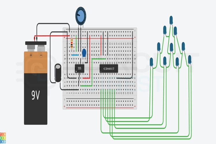
Building It Step-by-Step
Power Rails – Connect your positive supply (e.g., 9 V) to the power rail and ground to the negative rail.
555 Timer Setup – Place the 555 on the breadboard. Add the resistors and capacitors to configure the IC in astable mode.
Clock Connection – Connect the 555’s output (pin 3) to the CD4017’s clock input (pin 14).
LED Array – Attach each of the 10 LEDs to the CD4017 outputs (Q0–Q9), with a resistor in series to limit current.
Decoupling Caps – Add a 0.1 µF decoupling capacitor across the supply pins of each IC to ensure stability.
Final Checks – Double-check all connections, then power the circuit. LEDs should begin chasing in sequence.
Tips, Tricks & Troubleshooting
If no LEDs light up, verify the power polarity and that the 555 is oscillating correctly.
Dim LEDs usually mean missing or incorrect current-limiting resistors.
If the sequence jumps or stalls, ensure that the 555 output is solidly connected to the CD4017 clock input and that reset/enable pins are correctly tied low.
Adding decoupling caps near IC power pins can vastly improve reliability.
Where You Can Take It Next
Once you’ve mastered the basic chaser, the possibilities open up:
Extend the Sequence – Cascade extra CD4017s for more LEDs.
Bidirectional Chasing – Combine logic to reverse the chase pattern.
Sound-Reactive Patterns – Replace the 555 with a microphone-based trigger to sync LEDs to music.
This LED chaser project is a fantastic blend of fundamental electronics and dazzling visual results — whether you’re a beginner or an experienced maker, it’s worth building and sharing.