
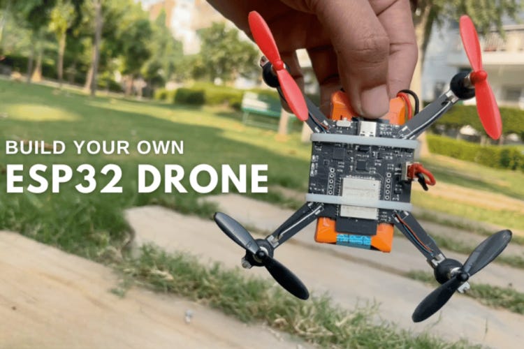
Building a Wi-Fi-Controlled Quadcopter with ESP32: An Engineer’s Walkthrough
From BOM to Firmware — How to Design and Fly a Low-Cost DIY Drone

1. Project Overview
This build uses an ESP32 WROOM as the core flight controller, combined with an IMU (the MPU6050) for stabilisation, WiFi connectivity for smartphone control, and a compact quad-rotor frame.
The goal: create a fully functional WiFi-controlled quadcopter at low cost (≈ US $30-50) with accessible, open-source components.
From an engineering perspective, this is a great platform because it covers power management, motor control via MOSFETs, sensor fusion, firmware flashing, and wireless interface — all in one.
2. Key Features & System Comparison
Some of the standout features:
WiFi control via smartphone app (instead of a traditional 2.4GHz RC transmitter)
MPU6050 IMU enabling 6-axis measurement (gyro + accelerometer) for stabilization
Compact PCB frame integrating the flight controller and power distribution — no separate bulky frame required
Upgrade path: open-source firmware so you can add height-hold, position-hold or gesture control.
In their comparison against a commercial drone controller:
Control method: WiFi smartphone vs RF remote.
Build cost: ~$30-50 vs $100-300 for typical commercial controllers.
Learning value: fully open source vs limited/modular commercial.
For an engineer building from scratch, this means more flexibility, more control, and more insight into the flight-control loop than off-the-shelf drones.
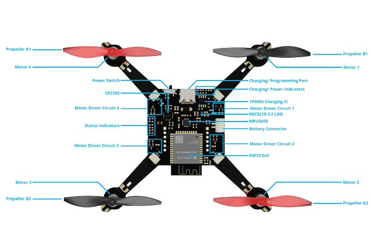
3. Bill of Materials & Hardware Breakdown
Here’s a selective snippet of the components and their roles:
ESP32 WROOM module – the microcontroller and WiFi interface.
CP2102N USB-UART controller – for programming the ESP32 and managing boot/reset signals.
MPU6050 IMU – for measuring orientation and motion.
TP4056 Li-ion charger IC – for safe battery charging via USB.
MOSFETs (SI2302, etc) – to drive the motors via PWM, and protect against back EMF.
720 core-less motors + 55mm CW/CCW propellers – the propulsion subsystem.
Custom PCB integrating power-management, motor drivers, controller, and mounting structure.
From an engineering viewpoint: you get power path switching (USB vs battery), voltage regulation (3.3V LDO), MOSFET-based motor drive, sensor interface (I2C), and WiFi comms — all on one board.
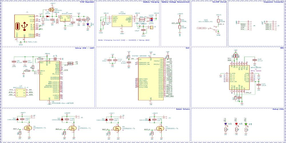
4. Schematics & PCB Design Considerations
The design integrates multiple subsystems:
Power subsystem: USB Type-C for both programming and charging; P-channel MOSFET + diode to switch between USB-power and battery.
Voltage regulation: MIC5219 3.3 V LDO to supply the ESP32 and sensors.
Programming interface: CP2102 USB-UART + dual MOSFET auto-reset circuit (removes boot-select hassles) for ESP32.
Motor driver circuits: Four discrete MOSFET driver paths, each with flyback diodes and pulldown resistors to safely drive brushless motors.
PCB integration: The board also acts as the frame mounting plate; the feet are included in the PCB fabrication.
From an engineering design lens, this offers excellent layout challenges: balancing minimal weight (essential for flight), EMI concerns (from motors and switching), strong grounding for sensors, and routing the WiFi antenna without interference.
5. Firmware & Software Setup
Here’s how the software stack breaks down:
The firmware is based on the ESP‑Drone firmware by Espressif Systems, modified for this custom PCB.
Supported build methods:
Build from source using ESP-IDF (v4.4.x) — engineer-friendly for customisation.
Use esptool.py to flash the binary directly.
Use the ESP32 Flash Download Tool (GUI) for ease.
After flashing: Power the drone, it creates a WiFi hotspot; connect via smartphone app (iOS or Android) to control take-off/landing and direction.
From your standpoint, you can modify the firmware to adjust PID parameters, add flight modes, add telemetry or expand sensors — a major engineering benefit.
6. Pre-Flight Checks & Operational Notes
Before you hit “fly”, the tutorial emphasizes:
Place the drone on a flat surface, power it on, connect via the app, and ensure LED status indicators show green (ready) or red (battery low).
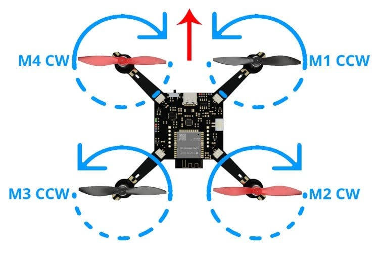
Check propeller rotation direction: front-right motor (M1) CW, front-left (M2) CCW, rear-left (M3) CW, rear-right (M4) CCW.
Use a battery with a sufficient current rating (they used 1300mAh 30C LiPo) — an underpowered battery causes instability.
Note: Flight time is modest (≈5-7 minutes with 1300mAh battery) and outdoors you’ll be vulnerable to wind since no GPS or advanced hold features are built-in.
As an engineer, you’ll appreciate that these constraints are real: weight vs battery capacity, control loop latency, sensor fusion accuracy, and wireless comm latency all impact flight stability.
7. Why This Build Matters & Where to Go From Here
Why it matters
Gives you full access: understanding the hardware, firmware, and wireless interface.
Encourages customisation: since open-source, you can experiment with sensors (barometer, magnetometer), GPS, telemetry links, or even computer vision.
Cost-effective: much cheaper than commercial platforms, great for experimentation or education.
Where to go next
Add altitude hold or position hold modules (barometer/GPS).
Upgrade motors/props for outdoor use and longer flight time.
Integrate camera or video transmission for FPV or aerial observation.
Upgrade the wireless link (e.g., add external antenna, switch WiFi channel, add fallback RF).
Tune the control loops (PID) for more aggressive flight or payloads.
8. Conclusion
This DIY ESP32 Drone presents a compelling engineering project: you build from the ground up, you learn the interactions between power, sensors, actuators and communication, and you end up with a flying system you can expand. If you’re an embedded systems engineer, hobbyist or educator looking to deepen your drone-tech know-how, this project provides a fantastic platform.