
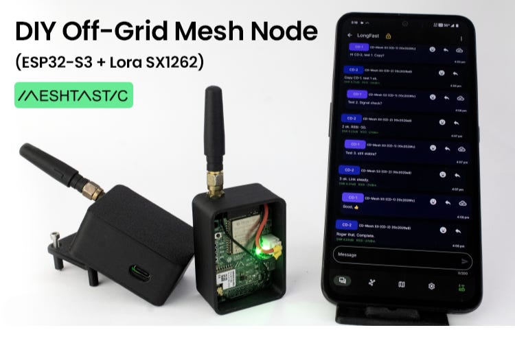
Building a Private Off-Grid Mesh Network with ESP32 and LoRa
How to design and deploy a cost-effective mesh node using the ESP32-S3 and SX1262 module for reliable off-grid communication

1. Why build your own mesh node?
Off-grid communications are increasingly important in applications such as hiking, disaster-response, remote sensing or agriculture where conventional cellular or WiFi infrastructure is unavailable or unreliable. The DIY ESP32 Meshtastic node highlights several motivators:
Stay connected without relying on mobile networks or the internet.
Achieve long-range communication, often spanning kilometres in line-of-sight.
Build a decentralised network (mesh) with no central dependency or single point of failure.
Obtain a cost-effective hardware solution, undercutting many commercial LoRa devices.
Allow customisation and expansion (sensors, GPS, displays, etc) because you control the hardware and firmware.
In short: if you need to deploy your own network in remote or infrastructure-challenged environments, this type of DIY node makes a lot of sense.
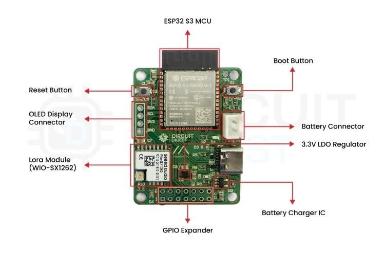
2. Hardware architecture at a glance
The core hardware for this project integrates four major functional blocks: microcontroller + wireless, power management, user interface/expansion headers, and enclosure. Let’s break them down.
2.1 Microcontroller & LoRa transceiver
The ESP32-S3 module (ESP32-S3-WROOM-1) is chosen for its dual-core architecture, WiFi & Bluetooth support, and sufficient flash/PSRAM for firmware and features.
The SX1262 LoRa transceiver (in a pre-certified Wio-SX1262 module from Seeed) handles the long-range radio link. Frequency bands depend on region.
These two form the communication engine of the mesh node: ESP32 runs Meshtastic firmware, SX1262 handles RF.
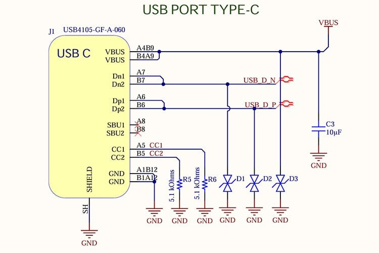
2.2 Power & battery management
The board includes a USB-C input port for power/charging. The circuit includes CC resistors and TVS diodes for USB-C design and ESD protection.
A Li-ion battery charger IC (LTC4054) is integrated to allow seamless switching between USB power and battery.
A 3.3 V LDO regulator (ADP124) supplies both ESP32 and SX1262 with stable voltage. Decoupling capacitors are carefully placed.
High-value resistors form a voltage divider that feeds the ESP32’s ADC pin to monitor battery level. This adds useful telemetry capability.
2.3 User interface / Expandability
The board has reset and boot-mode tactile switches (essential for flashing and debugging).
Status LEDs (green for alive, blue for charging) provide visual feedback.
GPIO header pins are broken out for expansion: sensor modules, OLED display header, etc. This turns the board into a platform rather than a closed box.
Antenna path: The LoRa module is placed at board edge; an optional PI-filter pad is provided for future tuning.
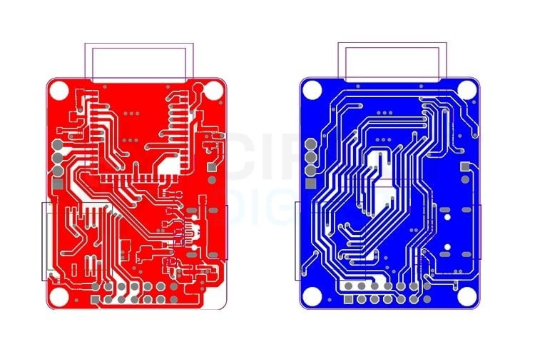
2.4 PCB layout & enclosure considerations
USB-C port is placed at board edge; traces from VBUS & GND are kept short and wide to minimise resistance and heating.
The ESP32 module is centrally placed; decoupling caps are placed close to VDD pins for signal integrity.
Ground stitching under RF section improves RF performance.
A two-part 3D-printed enclosure is designed: bottom tray for PCB & battery; top cover that snaps on; antenna cut-out and ventilation slots are included for field robustness.
3. Firmware, configuration & deployment
Once the hardware is assembled, you’ll move to firmware flashing, configuration and network deployment.
The firmware is based on Meshtastic for ESP32-S3 + SX1262 and is available via GitHub as per the project.
The recommended toolchain is Visual Studio Code + PlatformIO (preconfigured environment “CD-Mesh_S3”). This simplifies building and uploading.
After flashing, you pair your node with the Meshtastic mobile app (Android/iOS) over Bluetooth. Default PIN is 123456.
Use the web client (client.meshtastic.org) over USB to do full configuration (region/frequency, node name, channel key, role).
Important settings:
Region (e.g., IN865 for India) – ensures legal frequency band.
Channel key – same key must be used across nodes for private mesh.
Node role – router (fixed) vs mobile (battery).
Transmit power and radio preset (balance range vs speed) etc.
In test deployments: messages hop between nodes, even when nodes are out of direct link range, demonstrating mesh forwarding.
Optional features: position sharing (GPS enabled node or phone GPS via node), sensor data relay, custom payloads.
4. Practical applications & deployment scenarios
Here are examples of how this DIY mesh node can be used:
Outdoor recreation: Hiking or camping groups can deploy a few nodes across terrain to keep team members connected when phone signal fails.
Emergency communications: In disaster zones where infrastructure is disrupted, deploy a mesh of nodes to maintain local communication.
Agricultural/IoT monitoring: Scatter nodes across a farm to monitor soil moisture, temperature, etc and relay data across the mesh to a base station.
Remote research/field operations: For scientists working in remote areas, mobile teams and fixed nodes can stay connected without satellites/cell service.
Event coordination / off-grid gatherings: For festivals or volunteer operations in remote locations, a private mesh avoids overloaded mobile networks and provides local messaging and tracking.
The advantage is that you own the infrastructure, you control privacy and range, and you build flexibility into the system.
5. Key engineering take-aways
From an engineering standpoint, a few points stand out:
Integration matters: Combining microcontroller, radio module, power management and I/O headers into one PCB reduces assembly errors and improves reliability in the field.
Power and RF design are critical: USB-C port protection, battery switching, and clean 3.3 V supply are essential. On the RF side, board layout, ground stitching, module edge placement and optional tuning matter for performance.
Expandability adds value: By breaking out GPIOs, battery monitoring, display options and sensor headers, the board becomes more than just a communication node—it becomes a platform you can repurpose.
Mesh networking brings robustness: With multi-hop forwarding, the network can cover larger area with fewer nodes, and doesn’t depend on a fixed topology or central infrastructure.
Open-source firmware + custom hardware = flexibility: You’re not locked into commercial device limitations—modifications, sensor integration and tailored deployments are possible.
6. Getting started: checklist
If you plan to build this project, here’s a recommended checklist:
Order the PCB Gerber files (from the project) and components (ESP32-S3-WROOM-1, Wio SX1262 module, ADP124, LTC4054, passives, USB-C connector, battery header).
Assemble board starting from smallest passives → power management ICs → ESP32 module → LoRa module → connectors & switches.
Flash Meshtastic firmware using PlatformIO environment “CD-Mesh_S3”.
Configure the node via the app and/or web client: region, channel key, role, etc.
Deploy two or more nodes in field environment, place them with some separation, test message hops.
Optional: integrate sensor modules, attach GPS or OLED, add custom enclosure and test battery operation.
Monitor battery status over time, log network performance, iteratively optimise location/antenna.
7. Conclusion
The DIY Meshtastic node using ESP32-S3 and SX1262 is a strong example of how makers and engineers can build reliable, off-grid, private mesh networks with accessible hardware and open-source firmware. For scenarios where internet and cellular infrastructure are not available, this architecture offers a powerful alternative.